Example:
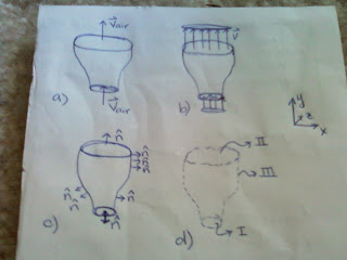
Let's consider the nozzle attachment on the hose of your vacuum cleaner (or your mom's vacuum cleaner). When we turn the vacuum on, air is sucked through the nozzle, as in Figure 1.A. The first step to finding a solution to the problem is to define a CV, like the one in Figure 1.D that contains all the air in the nozzle and is perpendicular to the flow into and out of the attachment. To make this example as simple as possible, we're going to make the simplifying assumptions that we are dealing with steady, laminar, incompressible, and uniform (or inviscid) flow. This means that our velocity profiles at the nozzle inlet and exit look like those in Figure 1.B.
Once again, the integral form of the continuity or conservation of mass equation for a control volume is:
0 = d/dt(int(rho)dV) + int(rho*(V.n))dA
If we look at the first term on the right side of the equation, we have:
d/dt(int(rho)dV)
Since our flow is steady, d/dt(anything) (how anything changes as time changes) is equal to zero because nothing is changing with time.
If we look at the second term on the right side of the equation, we have:
int(rho*(V.n))dA
Since our flow is incompressible, rho is constant and can mathematically be pulled out of the integral:
rho*int(V.n)dA
For this term, we are integrating over the entire control surface. It makes our lives easier if we divide the control surface into segments like Figure 1.D- control surface I is the disk at the nozzle inlet; control surface II is the disk at the nozzle exit; and control surface III is the "sleeve" along the inside wall of the nozzle attachment.
rho*int(VI.nI)dAI + rho*int(VII.nII)dAII + rho*int(VIII.nIII)dAIII
Remember we said that our velocity profile looks like Figure 1.B; thus, at every point on the nozzle inlet/exit, the velocity vector (VI or VII) looks like the ones in Figure 1.A. These vectors look like this:
Inlet (surface I): (0 |VI| 0) and Exit (surface II): (0 |VII| 0)
Along surface III, the air is flowing parallel to the nozzle surface (since we have assumed inviscid flow), making the velocity vector (VIII) here:
Surface III: (0 |VIII| 0)
Now what about that pesky n...the unit outward normal vector? This vector is different at every point along the control surface, as you can see in Figure 1.C. BUT this vector can always be determined because of its definition. Unit - means it always has a magnitude of 1. Outward - means that it is always pointing out of the control volume. Normal - means that it is always perpendicular to the control surface. So at every point on surfaces I and II:
nI: (0 -1 0) and nII: (0 1 0)
The unit outward normal vectors are different for different points on surface III, but we'll deal with that in a minute.
At this point we have every piece to the puzzle...I mean the continuity equation. We know all the velocity and unit outward normal vectors...we just have to put everything together. This means taking the dot product of V and n for each control surface segment:
I: VI.nI = 0*0 + |VI|*(-1) + 0*0 = -|VI|
II: VII.nII = 0*0 + |VII|*(1) + 0*0 = |VII|
III: VIII.nIII = 0 because VIII is always parallel to the surface and nIII is always perpendicular to the surface; thus VIII and nIII are perpendicular and the dot product is zero.
We now have:
rho*int(-|VI|)dAI + rho*int(|VII|)dAII
Again our assumptions that allow us to have the uniform velocity profile in Figure 1.B mean that the velocity magnitudes at I and II are constant and can be pulled out of the integral leaving us with:
rho*-|VI|*AI + rho*|VII|*AII
where AI and AII are the areas of these control surfaces. Putting allllllll of this information back into our original continuity equation, we get:
rho*|VI|*AI = rho*|VII|*AII
Density*velocity*area is known as a mass flow rate, so we can rewrite the above as:
mI = mII or min = mout
Or in words, the amount of air that enters the nozzle equals the amount of air that exits the nozzle. This makes physical sense because the nozzle itself is not expanding or contracting, and the amount of air in the nozzle remains constant.
It all boils down to this:
Mass can't be created or destroyed; therefore, if we have mass entering a control volume, either a) the amount of mass in the control volume must be changing with time (i.e. filling up a swimming pool) or b) the same amount of mass must be simultaneously exiting the control volume (i.e. our nozzle problem). The mathematical expressions presented in the continuity equation track how the amount of mass in the control volume changes with time and how much mass crosses into or out of the control volume; it is essentially an accounting equation that keeps track of mass.
I hope that this example has helped you better grasp the concept of mass conservation as well as the math in the expression. Please feel free to comment or ask questions, and until next time...happy trails!


0 comments:
Post a Comment